
Related Documentation: Technical Guide 1
This documentation describes procedures for converting between the physiological units often used in papers describing the results of electrophysiological experiments, and the SI units used in GENESIS 3. It also explains the relationship between common parameterized descriptions of channel gate rate functions and corresponding parameters in the Neurospaces Description Format (NDF).
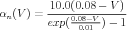
Section 3 of the GENESIS 3 Technical Guide 1 Technical Guide 1 explains the representation of a simple cell model containing Hodgkin-Huxley channels in the Neurospaces Model Container (NMC). Equations (15) and (16), restated below, give the forward and backward rate function for the kinetics of the squid axon potassium channel n gate activation, as fit to their experimental data by Hodgkin and Huxley.
|
| (1) |
 | (2) |
These are in physiological units, commonly used in experimental neuroscience, where voltage is measured in millivolts (mV ) and time in milliseconds (msec).
In GENESIS 3, the Model Container uses SI (meter, kilogram, second) units for stored parameters. Voltages are expressed in Volts, and currents in Amperes. Unfortunately, quantities typical of neurons tend to have either very large or very small values when expressed in SI units. For this reason, many people prefer to use physiological units.
Technical Guide 1 shows the PARAMETERS block of the NDF represention of the forward rate of Eq. (1) as:
PARAMETERS
PARAMETER ( HH_AB_Add_Num = -600.0 ), PARAMETER ( HH_AB_Mult = -10000 ), PARAMETER ( HH_AB_Factor_Flag = -1.0 ), PARAMETER ( HH_AB_Add_Den = -1.0 ), PARAMETER ( HH_AB_Offset_E = 60e-3 ), PARAMETER ( HH_AB_Div_E = -10.0e-3 ), END PARAMETERS |
This documentation gives further details of the procedures for converting between physiological and SI units, and the relationship between rate equations such as Eq. (1) and the parameters in the NDF PARAMETERS block above.
Any inconsistency in the units that are used can result in confusion as well as incorrect results. One way to keep confusion to a minimum is to stick to SI units. This is the approach taken in GENESIS 3, and with the GENESIS 2 Neurokit program and its associated prototype libraries of channels and other cell components. Although we are moving away from GENESIS 2 SLI scripting for new simulations, the GENESIS 2 prototype libraries will remain an important source of components to be used in GENESIS 3 simulations.
Table 1.1 presents a summary of the units used for common quantities ocurring in neural models and the conversion between physiological and SI units.
|
For a compartment of length l and diameter d the passive parameters in farads and ohms are related to the size-independent specific membrane capacitance CM, membrane resistance RM, and axial resistance RA by
 | (3) |
 | (4) |
 | (5) |
From the units given in Table 1.1 one can obtain the units and conversion factors given in Table 1.1.1.
|
Equations (1) and (2) have another difference from modern notation, in that the voltages were measured with respect to the resting potential of the squid axon (-70 mV ), rather than relative to the extracellular potential. GENESIS defines the default extracellular potential as 0 V . GENESIS 2 has traditionally used the global variable EREST_ACT as an offset to give more flexibility when implementing functions to create a channel. EREST_ACT is the nominal resting potential of the cell, which is -0.07 V in this case. By replacing V by V - EREST-ACT in the rate equations, we may use the channel with any assumed resting potential. This can be useful, for example, when using a Hodgkin-Huxley squid axon channel in a mammalian neuron model with a resting potential of -60 mV . When converting Eqs. (1) and (2) to SI units, the voltages would be converted with
 | (6) |
where Erest is the resting potential in mV , which in this case was defined to be zero. In other cases, Erest is likely to be the the same as EREST_ACT when expressed in mV , and would give a simple scaling of voltage rather than a scaling plus offset.
In addition to converting the voltages from mV to volts, the rate functions need to be converted from phyiological units (1∕msec) to the SI units of 1∕sec. This means that the rate functions should be scaled by a factor of 1000. As a result, Eqs. (1) and (2) become
 | (7) |
 | (8) |
From these, one can determine the values to be used in Eq. (12) of Technical Guide 1.
This conversion becomes much easier if the rate function can be expressed in one of the standard parameterized forms that are used in GENESIS. This is the case with Eqs. (1) and (2), and many other channels for which someone has already analyzed the experimental data and fitted the rate functions α(V ) and β(V ) to some equations. The squid channels and many of the other channels in the GENESIS channel library and the neurokit/prototypes directory have been put in such a form. For other cases, it is necessary to have the function that creates the channel use a for loop to evaluate the equation and to fill each gate table.
GENESIS 2 and the backwards compatibility module ns-sli have a command, setupalpha that can be used to create and fill the A and B tables when a gate has rate equations of the general form
 | (9) |
Note that this is a generalization of the three basic Hodgkin-Huxley forms EXPONENTIAL, SIGMOID, and LINOID. Eqs. (7) and (8) are of this form, so one can set up the tables for the n gate with a GENESIS 2 or ns-sli command of the form
setupalpha chan gate AA AB AC AD AF BA BB BC BD BF
|
where the parameters AA–AF correspond to those in Eq. (9) when it represents α(V ) and the parameters BA–BF correspond to those for β(V ).
The Hodgkin-Huxley squid axon n gate described by Eqs. (1) and (2), and used as an example in Technical Guide 1, is defined along with the sodium m and h gates in the GENESIS 2 channel prototype file neurokit/prototypes/hh_tchan.g. It contains the command
setupalpha {chanpath} X {10e3*(0.01 + EREST_ACT)} -10.0e3 \
-1.0 {-1.0*(0.01 + EREST_ACT)} -0.01 125.0 0.0 0.0 \ {-1.0*EREST_ACT} 80.0e-3 |
to set up the A and B tables for the potassium n gate, which is represented here as X in GENESIS 2 notation.
The parameterized gate description used in the NMC is given by Eq. (12) in Technical Guide 1
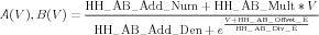 | (10) |
which applies when the constant HH_AB_Factor_Flag has its default value of -1. The constants appearing in Eq. 10 are used in the NDF PARAMETERS block, and are related to those in Eq. (9) by the table
|
If the rate equations are in physiological units, and can be expressed in the form of Eq. (9), possibly with a different resting potential, then Eq. (6) can be used to translate the voltages. If the lower case letters a, b, c, d, and f are used to represent the parameters in physiological units, then the SI parameters are:
A = 1000a - 106b(EREST
-ACT - 0.001Erest)
B = 106b
C = c
D = 0.001d - (EREST-ACT - 0.001Erest)
F = 0.001f
As an example, these relations may be applied to the forward rate function in Eq. (1), using Erest = 0 mV and EREST-ACT = -0.07 V to give the results for the parameters:
|
Note the correspondence between the values for the SI parameters in Table 1.3.1 and the NDF PARAMETERS block given in the Introduction.
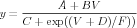
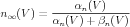
Sometimes, gates are described in terms of the voltage dependent steady state activation n∞ and time constant τn. These functions are more directly related to the results of voltage clamp experiments, and can be expressed in terms of the rate functions as
 | (11) |
 | (12) |
Some GENESIS 2 scripts for creating channels use the setuptau command to fill the gate A and B tables by specifying the time constant and activation with an equation in the form of Eq. (9) where the parameters AA – AF correspond to the time constant and BA – BF correspond to the steady state activation.
GENESIS 3 does not currently provide a parameterized representation in this form. In the future the sli_load command should translate setuptau commands into a NDF representation with a PARAMETERS block containing the table values, or other equivalent representation.
The conversion from these parameters in pysiological units to SI units is a slighty different from the setupalpha form, because the conversion equations for the time constant and steady state activation have different units. For the time constant parameters A – F, where τ is in seconds,
A = 0.001a - b(EREST-ACT - 0.001Erest)
B = b
C = c
D = 0.001d - (EREST-ACT - 0.001Erest)
F = 0.001f
The steady state activation is a dimensionless quantity, and the parameters A – F are
A = a - 1000b(EREST-ACT - 0.001Erest)
B = 1000b
C = c
D = 0.001d - (EREST-ACT - 0.001Erest)
F = 0.001f
Often, detailed voltage clamp data is not available for a channel to be modeled. In this case, it is common to roughly fit the steady state activation of gate to a sigmoid function, with a fixed voltage-independent value of the time constant τ. In this case,
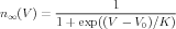 | (13) |
and τ is a constant. Here, V 0 is the voltage for 50% activation, and K is
related to the slope of n∞(V ) at its midpoint ( )V =V 0 by
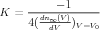 | (14) |
Equation (13) can be put in the setuptau form of Eq. (9), using A = 1, B = 0, C = 1, D = -V 0, and F = K. However, the voltage-dependent exponential term in the denominator presents a problem if τ is to be a constant. One way to deal with this is to use an approximation with A = τ , B = τ∕F, C = 0, D = 0, and F = 106.
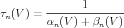
However, it is possible to put these in the setupalpha form. Equations (11) and (12) can be used to calculate the expressions for the forward rate α(V ) and the backward rate β(V ) in terms of τ and n∞(V ). Normally, one would not expect the resulting equations to be in the form of Eq. (9), but in this simple case, a little algebra yields the surprisingly simple result
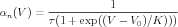 | (15) |
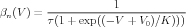 | (16) |
Thus, αn(V ) and βn(V ) are in the form of Eq. (9), with the parameters for αn(V ): A = 1∕τ, B = 0, C = 1, D = -V 0, and F = K. For βn(V ), they are the same, except that F = -K.
If τ, V 0, and K are given in physiological units, possibly with a different reference point for Erest, the equations in Sec. 1.3.1 may be used to convert them to SI units, and Table 1.3 may be used to convert them to the parameters used in the NMC parameterized notation.